|
0662
0662-Sxx
1.05 GB, 3.5x1, ???? RPM
Hot Plug/Unplug
Support
Power supply and SCSI bus hot plug and unplug is allowed.
There is no special sequence required for connecting 5 volt, 12 volt, or
ground. During a hot plug-in event the drive being plugged with draw a
large amount of current at the instant of plug-in. This current spike is
due to charging the bypass capacitors on the drive. This current pulse
may cause the power supply to go out of regulation.
If this supply is shared by other drives then a low voltage power on
reset may be initiated on those drives. Therefore the recommendation for
hot plugging is to have one supply for each drive. Never daisy chain the
power leads if hot plugging is planned. Hot plugging should be minimized
to prevent wear on the power connector.
Hot plugging the SCSI bus may cause glitches on the bus.
To minimize the chance of glitching, it is recommended to plug in the SCSI
bus before the power is applied.
During hot plugging, the supplies must not go over the
upper voltage limit. This means that proper ESD protection must be used
during the plugging event.
Option jumper blocks
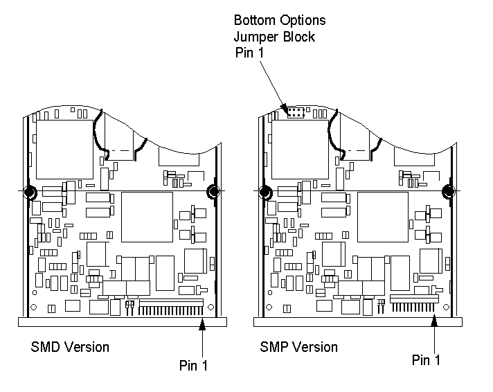
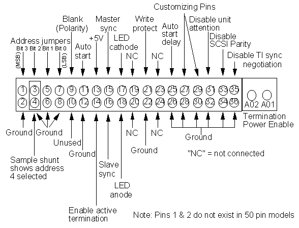
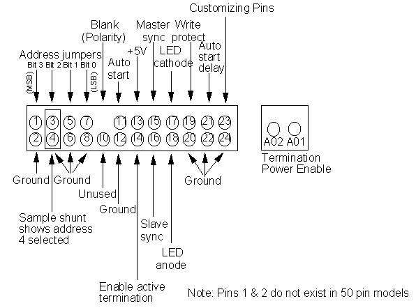
0662 contains a front jumper block with pins that can be used to access
and enable certain features and select the SCSI address of the drive. figure
3A shows the layout of those pins for the "SMD" version of the electronics
circuit board. For the "SMP" version of the electronics circuit board,
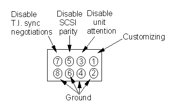
those functions are split into two groups of pins. The front block is shown
in figure 4A, while the block located on the bottom is shown in figure
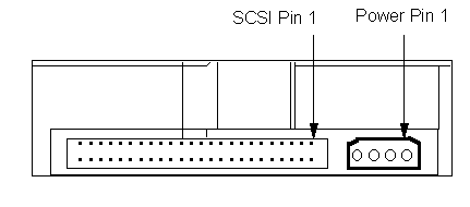
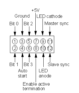
6. 68 pin models also contain a rear option jumper block that replicates
some of the functions contained in the front block. The layout of those
pins are shown in figure 7.
Drive Not Responding
From Mike King
I had this problem with my Server 9595-B20 which had six
0662 1GB drives on the RAID controller. I had maybe three drives
"not responding" when I started (the system had been out of use for some
months before it came to me), in each case the "not responding" drive had
failed to spin up. I find 0662s that are not used for a longish period
often are reluctant to start spinning but usually respond to a sharp rotational
flick in the plane of the platters (no DC power required) and its easy
to try if you have hot swap bays. In my case it was fairly easy to
start all the drives and restore the RAID volume.
Once started in this way the drives will continue to start
properly on power up as long as they don't lie on the shelf too long.
Actually 0662s often get a pretty bad press but I have never had one go
bad whilst in regular use.
Figure
1- SMD and SMP layouts
Figure
3A Front options jumper block for SMD versions
Figure
2 Electrical connectors (rear view) 50 pin SCSI
Figure
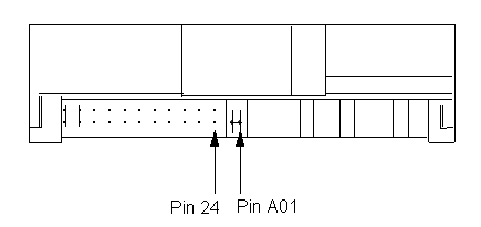
3 SMD jumper pin locations (front view)
Figure
4 SMP jumper pin locations (front view)
Figure
4A Front options jumper block for SMP versions
Figure
5A Address determination-50 pin SCSI models
|
Bit 0
|
Bit 1
|
Bit 2
|
Address
|
|
off
|
off
|
off
|
0
|
|
on
|
off
|
off
|
1
|
|
off
|
on
|
off
|
2
|
|
on
|
on
|
off
|
3
|
|
off
|
off
|
on
|
4
|
|
on
|
off
|
on
|
5
|
|
off
|
on
|
on
|
6
|
|
on
|
on
|
on
|
7
|
Note: In the address determination
tables above "off" means jumper is not in place and "on" means jumper is
in place.
Figure
6 Bottom options jumper block for SMP versions
Figure
7 Rear options jumper block for 68 pin models
Figure
8 Address determination-68pin SCSI models
|
Bit 0
|
Bit 1
|
Bit 2
|
Bit 3
|
Address
|
|
off
|
off
|
off
|
off
|
0
|
|
on
|
off
|
off
|
off
|
1
|
|
off
|
on
|
off
|
off
|
2
|
|
on
|
on
|
off
|
off
|
3
|
|
off
|
off
|
on
|
off
|
4
|
|
on
|
off
|
on
|
off
|
5
|
|
off
|
on
|
on
|
off
|
6
|
|
on
|
on
|
on
|
off
|
7
|
|
off
|
off
|
off
|
on
|
8
|
|
on
|
off
|
off
|
on
|
9
|
|
off
|
on
|
off
|
on
|
10
|
|
on
|
on
|
off
|
on
|
11
|
|
off
|
off
|
on
|
on
|
12
|
|
on
|
off
|
on
|
on
|
13
|
|
off
|
on
|
on
|
on
|
14
|
|
on
|
on
|
on
|
on
|
15
|
Note: In the address determination
tables above "off" means jumper is not in place and "on" means jumper is
in place.
Auto
start (& delay) pins
The auto start and auto start delay pins control when and how the drive
can spin up and come ready. When configured for auto-startup, the motor
spins up after power is applied without the need of a SCSI start unit command.
For no auto-start, a SCSI start unit command is required to make the drive
spin and be ready for media access operations. When in auto-start mode,
the drive will delay its start time by a period of time multiplied by its
own SCSI address. The table below shows whether or not auto-start mode
is active and the delay periods, where applicable, for all combinations
of the pins.
|
Auto start delay
|
Auto start
|
Auto start mode?
|
Delay multiplier (sec)
|
|
off
|
off
|
No
|
NA
|
|
off
|
on
|
Yes
|
0
|
|
on
|
off
|
Yes
|
10
|
|
on
|
on
|
Yes
|
4
|
LED pins
The LED pins can be used to drive an external light emitting diode.
Please refer to the LED pin section of the 0662 interface specification
for a detailed functional description of this pin.
o Up to 33 mA +/- 5% of TTL level LED drive capability is provided.
Note: These pins can be used to
drive an LED located in a bezel connected to the front of the drive or
to an external LED in systems where the front of the drive cannot be easily
seen.
Note: 68 pin SCSI models have two
sets of pins, a set on the front and a set on the back, that are connected
to the same LED driver circuit. The combined drive capability is stated
above.
Write protect
pins
If the write protect pin is jumpered to ground, the drive will inhibit
SCSI commands that alter the customer data area portion of the media from
being performed. See the 0662 interface specification for functional details.
Disable
T.I. sync. negotiation pins
If a disable target initiated synchronous negotiation pin is grounded
then an initiator is required to start a negotiation handshake if synchronous
SCSI transfers are desired. Please refer to the 0662 interface specification
for more details on this feature.
Disable SCSI
parity pins
Grounding this pin will disable SCSI parity checking.
Disable
unit attention pins
Grounding this pin will disable the drive from building unit attention
sense information for commands immediately following a power on reset (POR)
or SCSI bus reset. Any pending unit attention conditions will also be cleared
at POR or SCSI reset times.
Customizing pins
The customizing pins and their associated jumper pins are currently
reserved for future use. They are for features specific to particular host
systems that must be in effect immediately after power is applied to the
drive. Please contact your technical support representative for functional
details on using system specific required features that these pins could
possibly be used for.
Difference
between the -S12, S1D and -S1W
Model No of SCSI
SCSI No of
No
connector electrical
data heads
pins signal type
S12
50
SE
5
S1D
50
DF
5
SW1
68
SE
5
SWD
68
DF
5
Note: "SE" stands for single ended,
while "DF" stands for differential.
NOTE: The 0662 uses 6x32 mounting
screws, maximum allowable penetration of the mounting screws is 3.8 mm
SCSI bus termination power
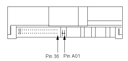
Termination power is optionally provided for systems that desire to
use it. In order to use the termination power, the user needs to install
a jumper between pins A01 and A02 of the termpower block. (Refer to figure
6 and figure 7). The jumper should only be installed on one device, which
should be the last device on the SCSI bus (ie, the drive that is physically
closest to a terminator). 68
pin models can source up to 2.0 amps of current at 5.0 volts (plus
or minus 5%) for termination power. 50 pin models can source up to 1.5
amps of current at 5.0 volts (plus or minus 5%) for termination power.
SCSI
bus termination power short circuit protection
The ANSI SCSI-2 specification recommends for devices that optionally
supply TERMPWR, to include current limited protection for accidental short
circuits. It also recommends that the maximum current available for TERMPWR
should not exceed 5 amps, UL has a different requirement that they call
the 8 amp rule. This rule states that when a power source leaves an enclosure
(like SCSI
TERMPWR in the SCSI cable), it must trip 8 amps of current within 1
minute.
0662 uses a resettable "Positive temperature coefficient" (PTC) resistor
for TERMPWR short circuit protection. These devices will trip when they
are over-heated due to excess current flowing through them. When the over
current condition (ie, current surge due to a hot plug or intermittent
short, or a solid short circuit) is removed, the device can automatically
reset, allowing TERMPWR to again be sourced from this device.
0662 complies with the 8 amp UL requirement. For systems that prefer
to with the SCSI-2 5 amp recommended TERMPWR limit, the 5 volt power supplied
0662 should be limited to prevent TERMPWR from exceeding 5 amps. This would
prevent a current surge in excess of 5 amps that may occur in the event
of a short circuit, before the PTC device can actually trip.
Attachment
to specific systems / SCSI controllers
The following SCSI Adapters have been evaluated with the 0662 drives
on typical MCA platforms with a range of operating systems. Any limitations
are noted below.
ADAPTEC 1640
FUTURE DOMAIN MCS-600
FUTURE DOMAIN MCS-700-Partition limit 1 GB
IBM Spock Prime
BUSLOGIC BT 6465
Fast SCSI
The ANSI SCSI committee recommend that fast SCSI devices (such as 0662)
must have cable lengths of less than 3 metres and must use active terminators.
NOTE: 0662 has onboard active terminators
which are jumper selectable.
Drives
Main Page
9595
Main Page
|


