8573 P75
rfp75a.exe
Reference disk for PS/2 P75 486 luggable
Mobile
System P75 (8573) IBM Parts ($$$!!!!)
P75 System Board
Indicator Port Pinout (J17)
Floppy Drive
Floppy Controller
2.88MB Capable?
External Storage
Device Connector
External
Storage Device Cable Source
Remove Floppy Drive (H1 Model)
Battery Pack
Processor Card
Video Card
Brightness Program
Hard Drive Removal
System Unit Fan (Remove/Install)
Power Supply Unit Checkout
Remove Power On Password
Built-in Features ADF
P75 Planar
78F9896
15F OKI 15F7917
4464 Hitatchi 4464S-08LL
82077 82077AA Floppy Controller
8032 80C32-1 CPU
Even, Odd SCSI BIOS 79F3214 E,
3213 O
F1-3 Fuses in power traces
F4 Fuse for floppy?
GA2 64F8781
GA3 79F3196
GA4 79F3242
GA5 79F3202
I7 Hitatchi 4464S-08LL
I56 79F3200
IC5F DMA Controller 90X8134ESD
J1 Keyboard
J2 Mouse
J3 Printer
J4 RS232C DB25
J5 External Floppy
J6 Display
J7 Bus riser
J8 PSU |
J9-12 72 pin SIMMs
J13 SCSI internal
J14 External SCSI C60
J15 Speaker
J16 Floppy
J17 Indicator
J19 Processor
J20 MC-2
J21 HDD Power
JP1 Power On Password
MC146818 MC146818AF
SCSI3 OKI 33F6910
SCSI7 33F6715
SI outline for 5 pin header, "SCSI
ID"
TP 8 pin Term Packs IR6-8
uCode PN 79F3212
X1 20.0000 MHz osc
X2 32.768k? xtal
X3 14.31 MHz osc
X4 24.0000 MHz osc
X5 20000 xtal KHz?
X6 12500 xtal KHz? |
J8 Wire Colors
Pin1 on left, pin 10 on right (silkscreened on board)
Blue (9), Orange (10), Red (11), R (12), R (5), Black (8), Bk (1),
Bk (2), Bk (3), White (4)
Numbers in parentheses are the corresponding power supply connector
Indicator Port
(J17) Pinout
This is the Indicator port- three LEDs are driven off
this header, Power, HD, and Floppy. Note that the header on the system
board and the display card (PN 65X1569) are keyed, so the pins match from
1 to 1, 2 to 2, and so forth.
Pin LED
1-2 Power LED
3-4 HD LED
5-6 FDD
Slot Numbers and Widths
The two upper slots are 32 bit. The slot next to the rear
cover has the AVE (dow! case is shut!) connector. The bottom two slots
are 16 bit, and they are short. FWIW, Slot 1 is the internal SCSI controller.
Slot 4
Slot 2 (Long)
32-bit AVE 32-bit
Slot 3
Slot 5 (Short)
16-bit 16-bit
P75 SCSI
This is a mix of the Adaptec AIC-6250EL, the OKI 15F7917, 33F6715 ,
33F6910 and the N80C32-1 cpu. To me, it resembles the short SCSI
/A.
SCSI BIOS PN 79F3214 (even) / PN 79F3213 (odd). SCSI microcode PN 79F3212
It uses three 8 pin SIPP term packs.
Up to six SCSI devices can be attched to the SCSI controller.
DMA Controller
90X8134ESD, just like on the K and 0 complexes and the 50Z planar.
J17 six pin header for floppy drive,
power, and hard drive LEDs
J20 MC-2 14 pin header that connects
to riser card.
Memory
2MB, and 4MB 70nS parity SIMMs are supported, maximum
16MB on the planar.
Load SIMM sockets from top to bottom, largest SIMMs (memory size) first,
smaller simms last. The notch in the SIMM goes to the left (towards the
outside of the case)
NOTE: If (4) 4MB SIMMs have been
installed, it may take up to 10 minutes for the IBM screen to come up when
reconfiguring with system programs. Or just using the system. Damn, it
counts slow...
Floppy Drive
The floppy can be used in the open
or closed position. It is recommended that it is operated in the closed
position so the chance of foreign material dropping in the drive
is greatly reduced.
The floppy in my P75 is a ALPS DFP723D15C, 12v
.47A, 5v .16A
Floppy Controller
It's a 82077AA. Probably supports 2.88MB floppy drives (yea!
got to love the dust shutter), but NOT the " *
" marked 2.88MB floppy drives.
2.88MB Capable
BIOS?
This is from the HMM- note the reference to a "4MB Media Sensor"....
3.5-Inch Diskette Drive 38F5936
3.5-Inch Diskette Drive 38F5936 (with 4MB Sensor)
External
Storage Device Connector
Shared with the P70, look HERE
Floppy Drive
Removal
I finally got Dr. Jim to speak in a way you can all understand
(Cult of Personality).
From Dr. Jim (I'm an engineer,
not a doctor)
OK, this is not rocket science, especially if you have
an H1 floppy.
Reach in behind the display panel with your left hand. Slide your index
finger in behind the floppy housing on the left side about 3/4 of
the way up. Then slide your finger downward along the edge of the
housing until it stops on the catch. At this point, hook your finger
behind the left side of the housing and pull the side of the housing to
the left, maybe 1/4" or so. Once the little post on the floppy cover
clears the catch, the floppy will flop forward.
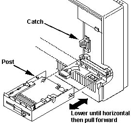 Continue
to rotate it until it is level, then pull it straight out. Continue
to rotate it until it is level, then pull it straight out.
Removing Floppy from Drive Carrier, H1 Model
Warning! There is
a aluminum ground shield across the bottom of the floppy drive. It is attached
with four screws through the bottom mounting holes (which are not used
by the plastic "rails"). It is coated on one side with a plastic non-conductive
coating. To properly attatch this shield, the grounding strap "tab" MUST
be on the same side as the motor! A simple test- use an ohmeter on the
shield, one side conducts, the other, not.
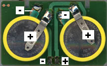
Battery Pack
PN 79F3198 (Entire assembly) Battery
Card, PN 64F8794
The P75 uses a 6V battery pack, with two Panasonic CR2477 3v
cells soldered to a circuitboard.
 The
battery header (J18) is a four pin header with one pin missing. The plug
on the end of the battery card cable has one position plugged. The
battery header (J18) is a four pin header with one pin missing. The plug
on the end of the battery card cable has one position plugged.
J18
- | +
-----------
O O X O
Battery Card plug "X" is plugged. "|" is open.
Processor Card
PN 64F8775 FRU 64F8789
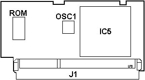
IC5 486DX-33
OSC1 66.6666 MHz
ROM PN 64F9924
P75 CPU
Upgrade (Dr. Jim Shorney's site)
Video Card
PN 78F9895 FRU 78F9897
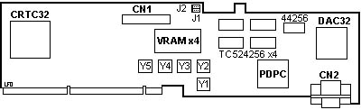
44256 Hitachi 44256S-10LL
CN1 Plasma panel
CN2 External video
CRTC32 TC110GC9AG
DAC32 37F0842
J1 Not a clue
J2 Not a clue
PDPC 53F8674 |
TC524256 Toshiba TC524256J-10
VRAM Toshiba TC524256AZ-10
Y1 25.175 MHz PC 640x480/ 400 modes
Y2 41.539 MHz PC 132-columns mode
Y3 28.322 MHz VGA / Text mode
Y4 44.900 MHz PC 1024x768 43.5Hz
(I) mode
Y5 40.000 MHz DMA Clock / 2
PC = Pixelclock |
A lot of these are used on the XGA adapter.
Any further info on the jumpers or chips? Tell ME!
Brightness
Program
To install Brightness program, run Brtinst.com from the refdisk.
This installs brt.com.
To have emphasized text brighter than standard text, type "BRT" and
press Enter.
To have standard text brighter than emphasized text, type "BRT /H"
and press Enter.
P75 System ADF
0E0FFh AdapterName "Built In Features"
Serial Port
The built-in serial port connector can be assigned as
Serial 1 through Serial 8, or disabled.
<SERIAL_1 03f8-03ff int
4>, SERIAL_2 02f8-02ff int 3, SERIAL_3 3220-3227 int 3, SERIAL_4
3228-322f int 3, SERIAL_5 4220-4227 int 3, SERIAL_6 4228-422f int 3, SERIAL_7
5220-5227 int 3, SERIAL_85228 -522f int 3, Disabled
Parallel Port
The built-in parallel port connector
can be assigned as Parallel 1 through Parallel 4 or disabled.
<PARALLEL_1 03bc-03bf
1278-127f int 7>, PARALLEL_2 0378-037f int 7, PARALLEL_3 0278-027f
int 7, PARALLEL_4 1378-137f int 7, Disabled
Parallel Port Arbitration Level
The built-in parallel port connector can be assigned any
one of the available arbitration levels 0 through 7. Select <Disabled>
to use the parallel port in compatibility mode.
<Level 6>, 5, 4, 3, 1,
0, Disabled, Level 7
Preempt Enable/Disable
Allows the system board processor to preempt continuous
data transfers by other devices for its use of the Micro Channel.
<Enable>,
Disable
Video I/O Address
This selects a particular I/O address range for the Display
Controller Registers. This field also affects the exact location of the
video coprocessor registers.
<Instance 6:
2160h - 216Fh>, Instance 1: 2110h - 211Fh, Instance 2: 2120h - 212Fh,
Instance 3: 2130h - 213Fh, Instance 4: 2140h - 214Fh, Instance 5: 2150h
- 215Fh
Video ROM Address Space
This defines the memory address range used for the
system video ROM.
<C0000 - C1FFF>,
C2000 - C3FFF, C4000 - C5FFF, C6000 - C7FFF, C8000 - C9FFF, CA000 - CBFFF,
CC000 - CDFFF, CE000 - CFFFF, D0000 - D1FFF, D2000 - D3FFF, D4000 - D5FFF,
D6000 - D7FFF, D8000 - D9FFF, DA000 - DBFFF, DC000 - DDFFF, DE000 - DFFFF
Video Arbitration Level
The video sub-system can be assigned
any one of the available arbitration levels 8 through 14.
<Arbitration level
13>, 12, 11, 10, 9, 8, 14
Video Fairness
Video Fairness indicates
whether or not the video sub-system coprocessor will follow the fairness
algorithm for bus usage.
<Fairness On>,
Fairness Off
Auto-Dim Time
Auto-Dim function automatically
turns the plasma display off after a specified period if no input from
the keyboard or auxiliary device is received. Auto-Dim Time can be assigned
from 1 to 120 minutes.
<10 Minutes>,
20 Minutes, 30 Minutes, 60 Minutes, 120 Minutes, 1 Minute,5 Minutes
Auto-Dim Reset
There are two ways to turn on the display again:
1. Pressing
SHIFT
2. Clicking
the mouse.
If the mouse picks up vibration
on a desk which turns on the display again, change Auto-Dim Reset from
<Keyboard and Aux. Device> to <Keyboard Only>.
<Keyboard
and Aux. Device>,Keyboard Only
Color to Gray Mapping
There are some applications that are developed
for color displays but can be used on monochrome displays. When using such
applications, reset Color-to-Gray Mapping to <Green Signal Only>. Setting
<RGB Mixed Signals> may result in an unpredictable display image.
<RGB Mixed Signals>, Green Signal
Only
Turned-on Display
Primary turns on only one display that
is considered by the system to be the primary display.
When no external PS/2 display is connected to the system unit, the plasma
display is considered as the primary display. Only VGA mode is supported.
When the external PS/2 display is connected, it is considered as the primary
display. VGA or XGA mode is supported for the external PS/2 display.
Plasma and External
turns on both the plasma display and the external PS/2 display. Only VGA
mode is supported.
<Primary>, Plasma
and External
9595 Main Page
|