8595 / 9590
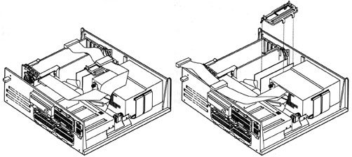
Model 90 Front View
Model 90 Planar
DBA Artifact on 8590s
Video Ram
Video RAM Installation
8590 and 9590 Planar
Differences
9590 Floppy Controller
Three Floppy
Experience
*
Marked 2.88MB Floppy Drives on 8590s
Serial Port Speed
Memory Riser
Orienting SIMMs on Riser
Loading SIMMs
Error 201
SIMM Holders
Riser
Support Bracket
Memory Expansion Boards
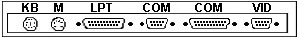
Front view
Badge- If grey, XGA. If blue, XGA-2
(Blue means ISO compliant).
Floppy 1.44MB (8590) or 2.88MB
(9590)
5.25" Bay Outer rails are for a
5.25" drive. The left and center rails are for a 3.5" drive.
Why was the 90 introduced?
Dennis Smith
The Model 90 was intended to be a "desktop server".
It came out in 1989/90. A few years before the Bermuda 77 and Lacuna
77. The 77 was the replacement for the Mod. 90, but it continued
in the 95xx Premium Line until about 1994. The main reason for releasing
the Mod. 90 was most likely to replace the Mod. 70 and to have a desktop
cousin to the Mod. 95.
Martin Adams
One advantage the model 90 has over the 77 is the 8 SIMM
slots. Eight 8M sims are allot cheaper than four 16M sticks right now.
We also have the caching SCSI that could have its cache upgraded. You don't
have to pull adapter cards to reconfigure RAM. I prefer the planar mounted
bus connectors too.
8590 / 9590 Planar
BT1 Battery
J1 SCSI adapter slot
J2 Power
switch/speaker
J3, J6 Adapter slot
J4 AVE slot
J5 Fan connector
J7 Processor-board slot
J9 XGA Video
J10 Power-on password
J11, J14 Memory-riser slot
J12 DB25
Serial Port
J15 Floppy
port
J16, J23 DBA ESDI port
J17 DB9 Serial
Port
J18 Parallel
Port
J19 Mouse
Port
J24 Keyboard
Port
J25, J26 Power-supply
Y1 32.768KHz
U7 DS1210
U9 41.5390 MHz
U13 14.3181 MHz "System Oscillator".
Timing for computer accessories, but not cpu or bus. |
U14 37F0842 Used on XGA cards
U16 TDK ZJY-2P g Used on XGA
U18 25.175 MHz Used on XGA
U19 TDK ZJY-2P g Used on XGA
U20 TDK ZJY-2P g Used on XGA
U21 44.9000 MHz Used on XGA
U22 28.3220 MHz Used on XGA
U23 Dallas DS1285 RTC
U24 SRM2264LC12
U25-U29 Video
Memory
U36, U38, U40 Video
Memory
U64 Toshiba TC110GC9AF (74F5160)
U65 40.0000MHz
U67 85F0464 Used on 95 M planar
U72 TI CF61533FN (64F3110)
U77 22.1184 MHz Clock for the "Type
3 High-Speed UART". Divided by 2 for better waveform and 1:1 ratio of low
and high.
U84 N82077AA Floppy Controller
U87 64F0942 Used on 95 M planar
U88 64F0942 Used on 95 M planar
U92 24.0000 MHz |
90 Ports
J16 and J23 Artifact-
IBM intended originally to bring out a "low-end" Mod. 90 with DBA-ESDI
and a 386DX-25 / DX-33 processorboard - but luckily dropped these plans.
(Ed. Either the US Army or a big insurance
company (different rumors) had 386DX-20 complexes made for it- the infamous
"Type 0"). The DBA-connectors are "design artifacts".
The planar adf for the Mod. 90 contains information on the DBA feature,
but they are no longer supported by the machine firmware or BIOS. Don't
bother with these ports, they are non-functional. The later Mod. 90 had
only soldering spots until the end of production.
Video Ram
The VRAM chips are Toshiba TC524256BZ-10 or NEC D42274V-10.
If you have a different Video ZIP make that works, send me a note.
The
8590 systems have 8 sockets for video memory available. The 9590 systems
come with 4 VRAM chips (512KB) soldered to the planar.
NOTE: Even though IBM Canada site
sez the 9590 has XGA-2 integrated into the planar, IT DOES NOT!!! It has
512K soldered on the planar, plus 4 sockets for the 512K video memory upgrade.
The 95xx just means ISO compliant. That's why the 9590 came with XGA-2
cards in them.
Video RAM Installation
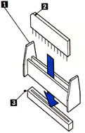
Place the insertion tool (1) over the emptyVRAM socket
(If you have one!)
Align the beveled corner (2) of the VRAM chip towards
the rear of the system. On most 90s, there is a dot on the planar that
the beveled edge (marked with a colored dot sometimes) lines up with. Carefully
align the pins with the socket (3) and firmly press the module
straight down into place
Do not start one end before the other. You can slightly
rock the chip side to side to install into a stiff socket, but be careful!
Which Slot for
the XGA-2?
Generally, Slot 2 or Slot 4. Slot 3 is physically incompatible.
For a full discussion, go HERE
Differences
between 8590 and 9590 Planars
The 9590 lacks the DBA artifacts, has 512K video memory soldered
on the planar, and is a pretty green. The 9590 planar is identified as
an XP 90 system board under setup. It does not support Synchrostream. The
parallel port is a standard one, no Expressprint. No Wake on Ring.
9590
Floppy Controller
On my 9590, it is a 82077AA If you know what it is on a 8590,
tell ME
about it!
Three Floppy Experience
Just because people said it isn't done, I threw three 1.44MB
floppies into my 9590. All three showed up under setup as 1.44MB drives.
Under DOS, they are accessable as A:, B:, and D:. Under W95, it blows the
mind of the IOS driver and Win95 says you must shut the system down and
restart Windoze. But under safe mode, I was able to access and read off
the D: floppy.
I will eventually try it under NT 4.0 just for snorts 'n grins...
* Marked Floppy Drives
on 8590s
Older 8590s may have their floppy controllers FRIED if
you use a 2.88MB floppy that has an asterisk ( * ) on the upper surface
of the eject button. The 9590 is not affected by this charming quirk. There
has to be an earlier floppy controller other than the 82077AA, which supports
an asterisk marked floppy on my 9590.
Serial Port
Speed
345.6KB/sec
Memory Riser
Orienting SIMMs
When inserting SIMMs onto the riser, orient the notch
on the SIMM with the notch on the riser. Always wondered why the riser
had that seemingly useless extension to the right. Think of the riser as
a big SIMM with it's notch. Like to like...
SIMM Holder Clips
There also was a problem with local power-drops on the early Mod. 90
memory riser cards (the ones with all-plastic SIMM-sockets). Improved versions
had metal holder clips. And - logically - you should not mix the two versions.
Memory
Riser Card Support Bracket
There *must* be a plastic Support Bracket clipped over the 2 (two !)
memory riser boards to properly fix them. This part is called "memory riser
card support bracket" and is FRU 57F3029. It also has a "bay" to guide
the SCSI-cable surface wave filter (that large heavy ferro-oxide block).
Loading SIMMs
Onto Memory Risers
Memory must be loaded in matched
pairs (size and speed) into sockets J1+J3 and J2+J4 for interleaved configurations.
(Type 1, 3, and 4 complexes). Type 2 complexes allow you to stuff SIMMs
in the sockets in any order or combination, but if not in matched pairs
(J1+J3, J2+J4) there will be a performance hit.
Don't stuff one Riser with modules (especially double-sided)
and leave the other blank. It *hates* imbalance on the memory drivers.
Try to organize them the way to achieve a balanced load on *both* memory
risers by having equal number of chips per pair, then on both risers.
Certain releases of the Mod. 90 had problems with the
double-sided SIMMs - especially with the 8MB ... I vaguely remember a sort
of pamphlet from IBM dealing with this issue - but cannot remember if I'd
copied it into a file or kept in in paper form and if: where I have left
it. At least the problem is not listed in the ECA-database.
Error 201
Error code 201 says "Reseat system board memory"
and can afflict the systemboard as well as the memory only. I would suggest
to remove the memory risers, reseat all modules, plug them back and see
if they are seated properly.
I would also suggest that you start with one single
pair of matching memory modules in the connectors J1 + J3
(Peter, pay more attention when you post!!!) on riser J11 - the one closer
to the processorboard. This is just to test out if your problem is memory-
or systemboard related.
If the machine comes up fine (counts memory) - install
the next pair in sockets J1 + J3 in Riser J14 - the on closer to the power
supply to keep balanced load of the memory decoder lines. As I wrote: the
Mod. 90 has a sensible feeling for imbalanced memory modules and may "spin
out" with somewhat strange and unexplainable errors by no obvious reason.
There once was a recommendation from IBM on that topic and they explicitely
mentioned it for the Mod.90 - particularly for those cases where double-sided
memory modules are used (which put a higher load on the decoder lines).
Memory
Expansion Boards
You can't. Sort of. The 90 will accept an expanded memory card's memory
IF there is less than 16MB on the risers. But IF the 90 has 16MB or more,
then setup disables the expansion board memory. If you can cram 64MB on
the risers, who the heck needs another 16MB on a card?
Planar Main Page
9595 Main Page
|