RAID
SCSI-2 RAID Controller
"Passplay" FRU 92F0335
SCSI-2 Fast/Wide
Streaming RAID Adapter/A
"Cheetah" FRU 06H3059
Create and Maintain your Array
Array technology, features, classifications(FWSR)
RAID Message Table
Hotswap bays for 95A
Removing side panel from 3 bay cage
Closeups of microswitches
Slots Passplay will fit
IML/Boot Limits of Passplays
HD LED Doesn't Work
>Is i a fact that the HD LED does not work on a 9595A with a PassPlay
RaidAdp.?
The fixed disk light is non-functional with both the Server
95 A "Passplay" and Streaming-RAID "Cheetah" MCA RAID adapter. I
suspect this is also the case with other OEM'ed Mylex RAID adapters.
Cheetah LED
BUT if you take an LED off of J6, pin 1 and 2, it will
light when the drives are accessed. Just run a lead up to between the LED
blocks in the display panel. Watch the polarity. If the LED doesn't light,
switch the header around. You do not need a resistor for this.
Tim Clarke
Hi gang,
just thought that I'd better warn you.
After checking out the Cyrix 5x86 at 4x clocking (in Type-1 non-SOD w/cache)
my PassPlay RAID adapter seems to have been "duffed up". I only get a part
of the BIOS v1.05 initialisation/installation message and the machine hangs
(with *any* CPU) at CP:96. Looks as though the Flash ROM has been partially
overwritten (just a guess).
Cache Size
>How important is the amount of cache ram on the PassPlay RAID adapter--4
MB, 16 MB, 64 MB? Under what circumstances will a cache increase
pay off? (The system in question is running NetWare 4.1, but I'm interested
in general info on this subject.)
I notice that the more recent Cheetah RAID adapter has
only 4 MB with no upgrade possible. It seems counterintuitive, but
I seem to remember reading somewhere that large amounts of controller cache
aren't really that useful with modern drives and operating systems.
From Peter
,,,Having a large cache is only half the truth. The bigger the cache
the bigger the damage if the controller chokes and cannot write back the
data to the drives. Large caches on Raid controllers make only sense if
they are battery-backed and if there is a mechanism that allowes to remove
the cache (with the data), replace the adapter, plug back the cache and
restart the system to that point where the operation was stopped and write
the cache data down to the drives and maintain the
integrity of the data / array.
The older Raid-controllers (Server-95 Raid "Passplay",
Fast/Wide Streaming Raid /A "Cheetah" and Fast/Wide Raid PCI "DAC960")
don't have battery backed cache. You should be aware of the fact that 4MB
of cache memory contain a large number of "data-stripes" (usually 8K blocks).
These will inadvertantly get lost if the machine powers
down by what reason, when the controller gets defective or the operating
system hangs. Recalculate how many sectors fit in 4MB - and the higher
the number of missing sectors the lower the chance that the Raid-Utility
will be able to restore the missing data.
On the other hand: the size of the cache depends on
a) the overall data-throughput of the drives (buffering x accesses
while the drives are in *mechanically* causes delay / dead zone / recalibration)
b) the size of the data-stripes (8K normally - 64K under WinNT might
give better results)
c) the operating system (WinNT and OS/2 are very "swap active")
d) the structure of the RAID itself (Raid-5 uses the cache much more
than Raid-1 ... because the mirroring is imminently fast with buffering
the data).
e) the nature of the data blocks. Consequently high internal redundancy
of the data will cause higher "hit rates" within the cache than permanent
data-streaming with new data, which void the cached data and only "pass
through".
Like on all caches there is a limit where enlarging the
cache any further makes no sense. And I think this limit is at around 4MB
on a 5 drives Raid-5 system running under OS/2 or WinNT. The content-redundancy
of the data is mostly not given - so the cache is mostly used to buffer
the Raid data-overhead between the drives (during reading / writing / synchronizing
the Raid structure) - on the transfer between drive-subsystem and processor
the cache does not play a major role.
A larger cache here costs only money and bears the above
mentioned risks to render the entire array useless if something crashes.
From "Mark"
Generally speaking, increasing the amount of cache will
always improve performance. The performance gain will be more for sequential
access type applications than for random access type applications. Typically
increasing the cache from 2 to 4MB will see a bigger % gain than 4 to 16
MB and that will see a bigger % gain than 16 to 32 MB and so on.
What version of the utilities do I need?
Both adapters use the same Utilities disk of the later
IBM F/W Streaming RAID Adapter /A (Codename "Cheetah" - with external port)
since both are based on Intel i960 / Mylex / NCR technology. There was
a single-disk version 2.22, which should be unique for all /A-Raid adapters
of that kind, but not the PCI-versions. The RAIDADM
(manager) should work on both /A-adapters.
The only thing they differ is the microcode, which *may
not* be interchanged. The SR95 adapter uses a microcode-level 1.6x
and (latest) 1.99, the FWSR uses 2.xx levels. If you flash the one adapter
with the code from the other you end up in non-functional adapters. (See
the README
coming with the 1.99-level microcode update for the Server 95 RAID adapter)
RAID
Supplemental Diskette Version 2.0 And the Readme.txt
RAIDSEND is a utility that provides an OS/2 ONLY command-line interface
for performing various tasks on a IBM F/W Streaming RAID Adapter/A, the
IBM SCSI-2 F/W PCI-Bus RAID Adapter, and the Mylex PL adapter for the IBM
PC Server 704.
NOTE:All systems, except the 95-466,
95-560, 95 A-466, 95 A-560 and 9585-0Kx, require that the standard SCSI
adapter or system board resident SCSI controller remain connected to the
IML and/or boot hard file.
SCSI-2
RAID Controller "Passplay" FRU 92F0335
SR
Flash BIOS ver. 1.61 Only for RAID controller WITHOUT an external port
on it!
SR
Flash BIOS ver. 1.62 Only for RAID controller WITHOUT an external
port on it!
SR
Flash BIOS ver. 1.63 Only for RAID controller WITHOUT an external
port on it!
SR
Flash BIOS ver. 1.99 Only for RAID controller WITHOUT an external
port on it!
Readme
for raid199a.exe (Server 95A RAID Flash disk version 1.99)
Server
95 Array RAID API Module (Non-ASPI)
Configuration Utility version 2.31
consists out of two disks:
FWSR
Option Disk, #1 ver. 2.31
FWSR
Option Disk, #2 ver. 2.31
Readme
for FWSR Option Disks
What's the Code, Kenneth?
From Hakan Gadler
By the way, why did they jump from version >1.6 something
to 1.99?
From Peter
IBM "unified" the version numbers for the BIOS and the
microcode a bit. Or - to be precise - the return codes. The later Passplay
codes ran along with the same RAIDADM software that was used by the "Cheetah"
and contained some better infos and other tweaks for performance / safety
reasons. From 1.63 on you could use the same RAIDADM and the later ServerGuide
Raid Manager for both adapters ... the previous versions seemed to have
delivered slightly odd codes
that confused mainly.
The Passplay was known for some misbehaviour to set drives
into "DDD" (Dead) state when they failed to come on ready in a very, very
short period of time after power on. This had beed fixed with the 1.63
code for most drives. The 1.99 codes contained some fixes for "other systems"
than the 95A. It was the last code announced for the Passplay.
The initial code 1.60 worked only with the early Passplay board releases.
Official shipping code at the time the systems were widely available
was 1.61 - which had some bugs with drives other than IBM 1.0GB (particularly
with the Maxtor MXT-540S in the "small" array configuration).
1.62 contained informations used by the 90MHz upgrade board - it is
mandantory if your 95A uses the "big" platform.
1.63 finally should fix problems with the DFHS 2GB drives (later microcodes
- successor of the 0664) and the "dead drive" symptom. As far as
I recall IBM recommended to use this code in all machines that have more
than 3 drives installed and the Pentium platforms (My guess: problems with
the power supply and signalling problems caused by DC-ripples).
Then IBM announced the 1.99 code "out of blue sky" and I wondered why,
because the Passplay was already discontinued at that time.
There are however some dependencies between the Raid-adapter
microcode and that of the processor board. You should not run the Raid
with a codelevel below 3 for the processor platform. The last codelevel
10 has been announced to fix Y2K problems with OS/2 AFAIK. If you flash
the processor platform to 10 and keep the old Raid microcode you might
run into problems. It should be 1.63 at least - especially if you have
the P90 platform, which appears to the Raid microcode as Server 500 with
the differing backplane layout - the return codes to the RAIDADM then might
not reflect the "real" position of the drives on the backplane.
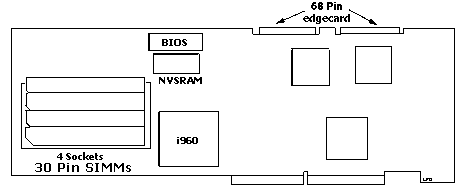
Fast Wide RAID Adapter (Passplay) FRU
92F0335

There is NO external port on the
Passplay!
Notes:
The 28 pin 8Kx8 NVSRAM is a Benchmarq, bq4010YMA-200,
Spec
sheet
Cable Parts of note: The mini C68 for the Channel edgecard connectors
is the Molex 71660i,
part# 15-92-3068, called a half pitch Centronics, or a VESA Media Connector.
Suprise! AMP makes a similar part (mini-C68) AMP Part 1-557089-2
Any cable with a .025 pitch, 28 to 30 AWG will work with either connector.
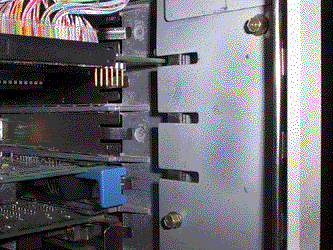
Slots Passplay
will Fit
The Passplay is an RS6000 form factor card (it's big). There
are cutouts in 8595, 9595, and 95A cases that will allow the edge of the
card at the bracket end to fit. Thanks to Dennis Smith, I was turned on
to them.
Slots 2, 3, and 4 have these cutouts- The 8595s do not
have a cushion in them, the 95As do.

IBM or Generic
SIMMs?
The 30-pin Simms should be standard industrial ("generic")
parts. Since the original concept allowed to go for 4 x 1, 4 x 4 and even
4 x 16MB cache Simms they *must* be generic, because IBM only coded the
256K, 512K and 1MB modules. The 4MB and 16MB are not on their list.
| SCSI type |
SCSI-2 Fast/Wide |
| SCSI bus path / speed |
16 bit / 20 MB/sec |
| I/O bus path / speed |
32 bit / 40 MB/sec streaming |
| I/O features |
Streaming data transfer |
| |
Address parity and data parity |
| RAID levels |
RAID 0, 1, Hybrid 1, 5 |
| |
4 ind (A, B, C, D) / 8 logical arrays |
| Tagged Command Queuing |
Yes |
| Processor |
i960 at 25 MHz |
| Size |
Type 5 (only fits Model 85 or 95) |
| Channels |
Two (both internal) |
| Connectors |
Two internal only |
| Devices supported |
7 devices per adapter |
| Cache std / max |
4 MB / 64 MB (with parity) |
| Cache method |
4 sockets for 30 pin 80ns SIMMs |
| Cache configurations |
4 16 or 64 MB only |
| Cache write policy |
Write-through or write-back |
| Available / withdrawn date |
N/A (Nov 1993 for Servers) |
SCSI-2
Fast/Wide Streaming RAID Adapter/A "Cheetah"
FRU 06H3059
Sidecard FRU 06H3060
194-170
19940517 IBM SCSI-2 Fast/Wide Streaming-RAID Adapter/A
FWSR Features
FWSR
Flash BIOS 2.21
FWSR
Flash BIOS Readme
Configuration Utility version 2.31
consists out of two disks:
FWSR
Option Disk, #1 ver. 2.31
FWSR
Option Disk, #2 ver. 2.31
Readme
for FWSR Option Disks

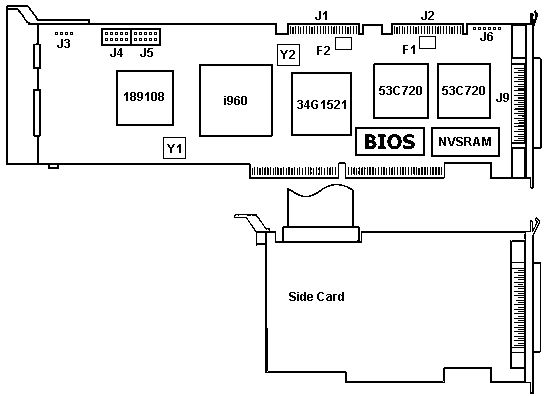
J1 Channel 1 68 pin edgecard
J2 Channel 2 68 pin edgecard
J3 Not connected. Or used.
J4 DASD Status Connector
J5 DASD Status Connector
J6 Possible serial port. Unused. |
J9 Channel 2 external port.
Y1 50 MHz Oscillator
Y2 40MHz Oscillator
F1 Channel 2 PTC resistor
F2 Channel 1 PTC resistor
|
Channels
The Cheetah has two channels. Each channel is controlled
by an NCR53C720. The header J1 is Channel 1. It usually is attached to
an internal array, but with the addition of a side card, it can controll
an external array. The second channel uses J2 OR the external port, J9.
This is still one channel, so one can use either the internal port, OR
the external port. Do NOT try to use both J2 and J9 at once.
Notes:
NVSRAM is a Benchmarq 28 pin 8Kx8 bq4010YMA-200, Spec
sheet
Another equivalent is a Dallas DS1225Y-200, spec
sheet
Function of the NVSRAM
Each NV SRAM has a self–contained lithium energy source and
control circuitry which constantly monitors VCC for
an out–of–tolerance condition. When such a condition occurs, the lithium
energy source is automatically switched on and write protection is unconditionally
enabled to prevent data corruption.
Cable Parts of note: The mini C68 for the Channel edgecard connectors
is the Molex 71660i,
part# 15-92-3068, called a half pitch Centronics or a VESA Media Connector.
Suprise! AMP makes a similar part (mini-C68) AMP Part 1-557089-2
Any cable with a .025 pitch, 28 to 30 AWG will work with either connector.
Server Backplane Address Jumper Configuration
Symptom : Servers with hot-swap backplanes may experience intermittent
drive errors, defunct (DDD) drives that don't spin down or drive LEDs that
don't blink when a drive has failed.
Problem Isolation Aids : The system is an 8640, 8641, 8642 or
3518 with one or more hot swap backplanes installed.
Fix :
Check the Backplane Address Jumper:
1. Shutdown the operating system
2. Power off the server.
3. Verify the Backplane Address Jumper configuration:
a. For ALL 8640 and 8641 backplanes:
Jumpers should NOT be present on the pins for Bank0, Bank1, or Bank2 on
any backplane. Refer to Figure 1. The PC Server 520 (8641) may have shipped
with a backplane address jumper installed; it should be removed.
b. For 8642 and 3518 backplanes:
Each backplane MUST have a unique address. A jumper should be present on
the pins for Bank0, Bank1, OR Bank2 depending on the backplane's location
within the server or expansion enclosure. Refer to Figure 1 and Table 1
below to determine the correct jumper setting for an 8642 or 3518 backplane:
Figure 1
Backside of Backplane
.------------------------------------------------------------.
| -----
----- |
| |
|
| | |
| | S |
| S | |
|.. Bank2 | C |
| C | |
|.. Bank1 | S |
| S | |
|.. Bank0 | I |
| I | |
| |
|
| | |
| -----
----- |
--------------------------------------------------------------
Table 1
|
Jumper Position
|
Backplane Location
|
|
Bank0
|
Bank C
|
|
Bank1
|
Bank D
|
|
Bank2
|
Bank E
|
Note :
The documentation in the Server 520 User's Handbook,
part number 62H7096, page 177 is incorrect. Backplane address jumpers should
NOT be installed on any Server 520 backplanes.
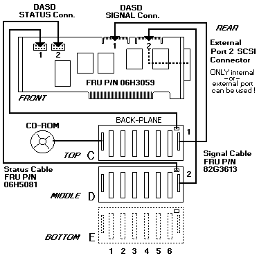
Cheetah in a Server 500

720 Backplane
Hot-Swap Backplane (FRU No. 06H8388)


I believe this is the Hot Swap Backplane III. Prove me wrong if you
can...
SCSI ID Jumper
If two backplanes are connected to the
same adapter, one backplane must be set to high and the other one to low.
|
SCSI ROM Address ID Jumper Setting
|
Description
|
|
HI=High
|
Assigns SCSI IDs 8 to D to the backplane
|
|
LO=Low
|
Assigns SCSI IDs 0 to 5 to the backplane
|
ROM Address Jumper Setting
Notes
a. If more than one backplane is installed
in the computer, each backplane must have a different ROM address setting.
b. Do not install a ROM address jumper on backplanes installed
in PC Server 320 computers.
c. To identify the location for the backplane jumper, see 'Hot-Swap
Backplane (FRU No. 06H8388)´.
|
Jumper Position
|
Description
|
|
C
|
Address for a backplane installed in Bank C
|
|
D
|
Address for a backplane installed in Bank D
|
|
E
|
Address for a backplane installed in Bank E
|
Termination (Hot-Swap Back Plane)
The hot-swap back plane is automatically terminated. Drives
connected to the hot-swap back plane should not be terminated.
Cheetah Specs
| SCSI type |
SCSI-2 Fast/Wide |
| SCSI bus path / speed |
16 bit / 20 MB/sec |
| I/O bus path / speed |
32 bit / 40 MB/sec streaming
(80 MB/sec on PC Server 720) |
| I/O features |
Streaming data transfer
Address parity and data parity |
| RAID levels |
RAID 0, 1, Hybrid 1, 5
4 ind (A, B, C, D) / 8 logical arrays |
| Tagged Command Queuing |
Yes |
| Processor |
i960 at 25 MHz |
| Size |
Type 3 (full length) |
| Channels |
Two (one internal; one internal or external) |
| Connectors |
Three total: |
| |
Two internal - 16 bit wide
(sidecard not included on Server 500)
One external - 16 bit wide
*Can only use two connectors at once |
| Devices supported |
14 per adapter (7 per max per channel) |
| Cache std / max |
4 MB / 4 MB (with parity) 60 ns |
| Cache method |
Soldered on adapter |
| Cache write policy |
Write-through or write-back |
Controllers
Main Page
9595
Main Page
|


